Excitation Systems
Excitation frameworks can be characterized as the framework that gives field current to the rotor twisting of a generator. All around planned excitation frameworks give unwavering quality of task, security and quick transient reaction.
The four basic excitation techniques include:
- Shunt Method or Self Excited Excitation System
- Excited Excitation Boost System (EBS)
- Permanent Magnet Generator (PMG)
- Assistant Winding (AUX).
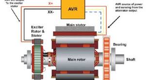
Every technique has its individual focal points. All techniques utilize an Automatic Voltage Regulator (AVR) to supply DC output to the exciter stator. The exciter rotor AC power yield is redressed to a DC contribution for the fundamental generator rotor. Further developed frameworks utilize an extra contribution to the AVR.
This article investigates the development, capacity, and application for every technique and incorporates charts and outlines for each.
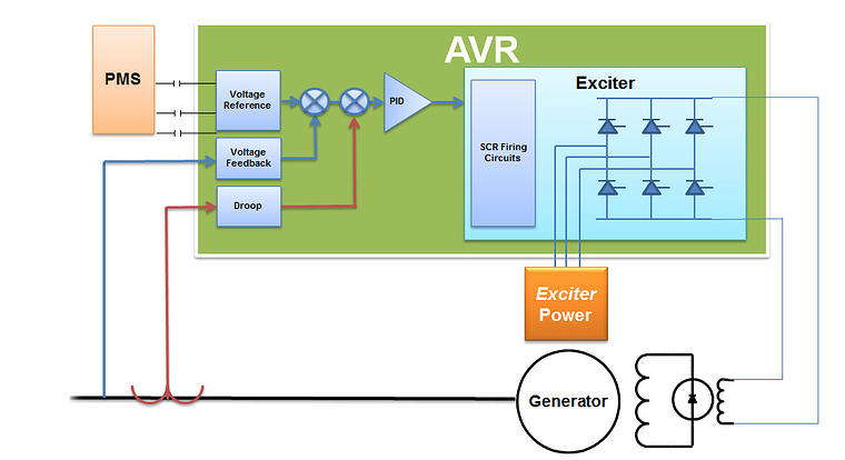
Automatic Voltage Regulator (AVR)
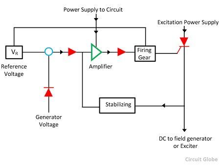
The development of the AVR differs from the excitation utilized. All get contributions from the stator of the generator when it pivots. AVRs with the capacity of getting a moment contribution to lessen or wipe out inward music caused by stack input signals are utilized for non-direct load applications. The two kinds normally utilized are:
Silicone Controlled Rectifier (SCR) – Senses power level from the stator and decides its terminating for the exciter voltage. Can cause inconveniences when utilized with non-straight loads.
Also read: Tips on Buying a Used Diesel Generator
Field Effect Transistor (FET) – Senses power level from the stator and makes an interpretation of into a Pulse Width Modulated (PWM) flag to the exciter. This style of AVR, also called field flashing, can be utilized for excitation strategies. Non-straight loads don’t cause input coming about excitation breakdowns.
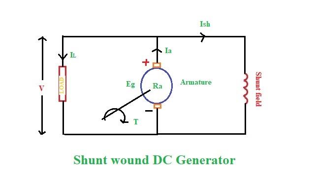
Shunt or Self-Energized Excitation System
The shunt strategy highlights a straightforward and practical plan to give include power to the AVR. This technique requires no extra segments or wiring. At the point when issues emerge investigating is rearranged with fewer segments and wiring to approve.
As the generator is pivoted, the stator supplies input voltage to the AVR. Moreover, the AVR has sensors that screen the yield of the stator.
The AVR acts as the power system stabilizer. It supplies power to the exciter which is redressed to the DC current. The current is then prompted onto the stator for stack yield.
The greatest disadvantage to this static excitation system the AVR is affected by the heap the generator is powering. At the point when the heap builds the voltage starts to diminish and the AVR must give more present to the exciter to help the request.
This pushes the AVR as far as possible. On the off chance that the AVR is pushed past it restrains the excitation field breakdown. The yield voltage is diminished to a little sum.
In the event that a short out happens in the supply to the AVR, the generator won’t have an excitation source. This causes lost generator power yield.
Generators with shunt or self-energized strategies can be utilized on direct loads (consistent load). Applications that have non-straight loads (differing load) are not suggest for generators with this excitation technique. Sounds related to non-straight loads can cause excitation field breakdowns.
Excited Excitation Boost System (EBS)
The EBS framework is contained a similar essential parts providing contributions to and getting yields from the AVR. The extra segments in this framework are:
- Excitation Boost Control (EBC) Module
- Excitation Boost Generator (EBG).
The EBG is mounted on the determined end of the alternator. Physical appearance is the same as a changeless magnet. The EBG supplies power to the controller as the generator shaft pivots.
The EBC control module is associated in parallel to the voltage regulator (AVR) and the exciter. The EBC gets motion from the AVR. At the point when required the controller supplies shifting levels of excitation current to the exciter at levels that rely upon the necessities of the framework.
The extra power sustained to the excitation framework underpins stack necessities. This enables the generator to begin and recoup the excitation voltage.
This excitation framework isn’t prescribed for continuous power applications. It is proposed for crisis or go-down power applications. At the point when the generator begins the EBS framework is separated until the point when the operating rate is come to. The EBG is as yet generating power however the controller does not course it.
The framework takes into consideration dynamic reaction, is more affordable and meets necessities for giving 300% short out current. Non-straight loads, for example, engine beginning, are enhanced when contrasted with the Shunt or Self Excited strategy.

Permanent Magnet Generator (PMG)
Synchronous generators outfitted with changeless permanent magnets are among the most understood independently energized strategies. A perpetual magnet is mounted on the determined end of the generator shaft.
Modern excitation systems such as the PMG supply separated power to the AVR when the generator shaft pivots. The AVR supplies power by using the additional power when providing non-direct loads, for example, the beginning of engines.
A spotless, disengaged, continuous 3-stage waveform is created when the generator shaft is turning.
Some of the most prominent advantages of utilizing generators outfitted with the PMG excitation technique are:
- The excitation field does not crumple taking into account managed cut off to clear.
- Changing the burden does not affect the excitation field.
- Voltage is made on introductory startup and does not rely upon outstanding attraction in the field.
- Amid engine start-up excitation field does not fall in view of the absence of AVR supply.
The PMG System adds weight and size to the generator end. It is the most normally utilized excitation technique for applications that utilization engines that start up and shut down and other non-straight loads.
Assistant Winding (AUX)
The assistant winding strategy has been being used for quite a long time. The utilizations go from marine to industrial applications and are more functional in bigger establishments.
This strategy has a different excitation field, nonetheless it doesn’t utilize a segment connected to the determined end of the pole of the generator. These techniques utilize shaft revolution and a perpetual magnet or generator to supply the extra excitation.
An extra single stage winding is introduced into the stator. As the generator shaft turns the stator principle windings supply voltage to the AVR as in all previously mentioned techniques.
The extra single stage windings supply voltage to the AVR. This makes the additional excitation voltage required when providing non-straight loads.
For straight load applications shunt, EBS, PMG and AUX excitation strategies can be utilized. Shunt excitation is the savviest strategy.
For non-straight load applications, EBS, PMG, and AUX excitation strategies can be utilized. PMG excitation is the most well-known and broadly utilized.
Frequently Asked Questions about excitation in generator:
What is an exciter?
An exciter helps in producing a magnetic field by supplying electric current which can be in the form of a battery or generator.
Why do generators need excitation?
Mechanical energy is turned into electrical energy by moving electrical conductors in a magnetic field with the help of generators. Excitation creates this electromagnetic field which initiates the conversion.
What happens when the generator loses excitation?
When a generator loses its excitation, the current in the rotor gradually decreases and the field voltage decays by the field time constant as well. In such a case, the generator and draws reactive power by acting as an induction generator, from the power system instead of generating reactive power.